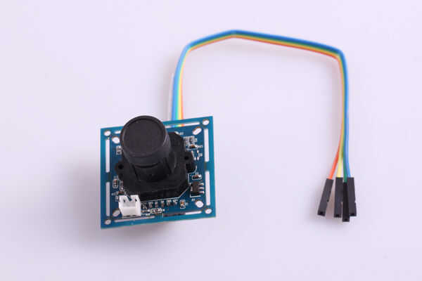
Cámara robótica controlada mediante un joystick, que gobierna dos servos estándar, proporcionando dos ángulos de rotación.
- 406 views
- 0 comments
- 0 respects
Arduino robot with GoPro camera and FPV function controlled from iPhone via Bluetooth or obstacle avoidance with ultrasonic sensor. A robot that has ultrasonic sensors mounted on a basic servo to detect obstacles, swerve around them, and continue on a random path! Monocle: View & Control IP Cameras with Alexa & Arduino. The electronics for a simple camera slider, keeping it simple so it can be used with an ATTiny85. A funny looking robot in the form of a plant, that interacts with some sensors inputs, talks, plays music. This guide is for our new TTL serial camera module with NTSC video output. These modules are a nice addition to a microcontroller project when you want to take a photo or control a video stream. The modules have a few features built in, such as the ability to change the brightness/saturation/hue of images, auto-contrast and auto-brightness adjustment, and motion detection. ArduCAM is a startup company dedicated to open source hardware and software, designed and manufacured in China specifically for Arduino and Raspberry Pi camera solutions. We also offer customized turnkey design and manufacturing solution services for.
Components and supplies
| × | 1 | |
| × | 1 | |
| × | 1 | |
| × | 1 | |
| × | 2 | |
| × | 2 | |
| × | 3 | |
| × | 8 | |
| × | 1 | |
| × | 1 |
About this project
Nuestro centro de educación secundaria forma de un programa para el desarrollo del pensamiento computacional y para el aprendizaje de nociones báscicas sobre programación y robótica. En el proceso de desarrollo de dicho programa hemos realizado diferentes prácticas y proyectos en los que hemos debido de poner en práctica los conceptos de los distintos bloques que forman el curso.Hemos elegido describir el proyecto de 'Cámara Robótica' que consiste en una webcam cuyo movimiento está producido por el giro de dos servos estándar, controlados por un joystick. Por un lado la placa a la cual están conectados los servos y el joystick esta controlada por el IDE de Arduino y, por otro lado la webcam lo está por el IDE de processing. Por lo tanto dos programas actuan simultaneamente.
Las piezas y los componentes electrónicos de los que consta el proyecto son las que aparecen en la siguiente imagen
Para su realización primero se han de ensamblar las piezas que forman la estructura, mientras se pasan los cables y se conectan los servos.
Por otra parte el programa que controla los servos mediante el joystick se ha de subir a la placa de arduino 101 y desde dicho programa se da acceso a el visionado de la cámara mediante el IDE de processing.
Code
Schematics
Created by
CTC 101
Are you CTC 101? Claim this project and add it to your profile.
This is minePosted by
Camara Arduino Programacao
Daniel_Poveda
- 0 projects
- 0 followers
Published on
June 10, 2019you might like
Table of contents
This post is a tutorial on how to get started on programming your Arduino in Assembly or C/C++. In order to follow you need a Windows machine and a microcontroller programmer like the Atmel-ICE.
Download the Visual Studio based IDE Atmel Studio from atmel.com/tools/atmelstudio.aspx. Follow the installation instructions.
Start Atmel Studio and create a new project (Ctrl+Shift+N). You can choose either C/C++ or Assembler.
On the next screen you will be prompted to select your device. Make sure you select exactly the one you are using. For my Arduino Uno that is “ATmega328P” (“ATmega328” would not work).
After selecting your device the code editor appears. The following two snippets implement the Arduino Blink Example in both C and Assembly. The output pin is the Arduino pin D13, which is the fifth pin in the PORTB register. The delay between on and off is 1000ms.
Blink in C
The well-known Arduino Blink sketch implementation in plain C. Note that functions like digitalWrite or delay do not exist. Port manipulation and external header files need to be used instead. The microcontroller’s clock frequency (here $f=16text{MHz}$) needs to be defined as well.
Blink in Assembly
Even more complicated: The Blink-sketch in Assembly. While being hard to read without the comments, this very low-level and probably the coolest version.
While the main program is relatively easy to understand, it’s probably not obvious, how the delay_1000ms function works (thanks to Ido Gendel for investigating on that). On a $16text{ MHz}$ clock the task of a one-second-delay-function is essentially to keep the CPU busy for 16 million clock cycles.
- The first three
ldi(“Loads an 8-bit constant directly to register 16 to 31.“) instructions take three cycles in total. subitakes one cycle as well and “subtracts a register and a constant, and places the result in the destination register Rd.” The constant is0x01in the snippet and the execution time is once again one clock cycle.- Each of the following two
sbciinstructions “subtracts a constant from a register and subtracts with the C Flag, and places the result in the destination register Rd“. The constant is0x00in both cases so the only thing that is subtracted is the C Flag. The C Flag however is only set, if the previous subtraction has resulted in an underflow ($0-1rightarrow255$). - Finally, the
brneinstruction “[…] tests the Zero Flag (Z) and branches relatively to PC if Z is cleared.” This takes two cycles if it branches, otherwise one.
When going through the statements step by step that leads to a total number of $n$ clock cycles for the subroutine body: $$begin{align}n=&3+256cdot212cdot5+256cdot256cdot48cdot5-1=&16,000,002,.end{align}$$
To actually see an LED blink, you have to connect your Arduino to a power supply and to your programmer. Connect the programmer to your PC.
Make sure the connection plug is facing into the right direction. If not it won’t cause any damage but you will encounter an error during the upload.
Run

Now hit the Run button in Atmel Studio (hotkey F5). The IDE will prompt you to select a programmer (“Please select a connected tool and interface and try again.”).
(1) Select your programmer (e.g. “Atmel-ICE”) and the (2) ISP interface. Also make sure you (3) uncheck “Preserve EEPROM” in the programming settings section. Now you should be able to upload your code (hit F5 again).
The Arduino bootloader needs to be flashed back onto the Arduino, before it can be used in combination with the Arduino IDE again. Starting Electronics has a post that explains how this can be done: Burning the Bootloader to an Arduino Uno using Atmel Studio
Camera Arduino Programme
Troubleshooting
See Atmel-ICE User Guide and AVRISP MkII Troubleshooting if the following sections do not help.
Failed to set-up tool (no context id returned)
Camara Arduino Programa De
Open the Device Pack Manager (Tools > Device Pack Manager) and install all updates.
Failed to launch program
Error: Failed to start programming session before chip erase with eeprom preserve:Failed to enter programming mode. ispEnterProgMode: Error status received: Got 0xc0, expected 0x00 (Command has failed to execute on the tool)
This could be a connection issue (e.g. the ISP plug is connected the wrong way around). It could also be that your microcontroller is not supplied with power.
Unable to start debug session
“Atmel Studio was unable to start your debug session.
Please verify device selection, interface settings, target power and connections to the target device. Look in the details section for more information.”
In order to write your own, more complex C/C++ or Assembly programs you are definitely going to need your microcontroller’s data sheet at hand:
Very important for Assembly projects is also the AVR Instruction Set Manual.

Camara Arduino Programa Download
Also note that you can view the generated assembly code after compiling a C/C++ project. That can be a good resource for improving assembly skills or for deeply understanding what’s going on behind the scenes. In order to look into the assembly code open the “Solution Explorer”, expand “Output Files”, and open the “.lss” file.